
Optimizing Manufacturing with Advanced Pneumatic Systems and Automation
Table of Contents
- 1 The Role of One-Way Valves in Industrial Automation
- 2 Technical Designs and Types of Air Compressor Check Valves
- 3 Strategic Valve Placement Across Compressor Technologies
- 4 Troubleshooting and Maintaining Pneumatic One-Way Valves
- 5 Frequently Asked Questions about Industrial Automation Valves
- 6 Conclusion
The Role of One-Way Valves in Industrial Automation

Modern manufacturing demands high efficiency and reliable operations. Pneumatic systems are essential for many industrial processes. These systems rely on various components, including Industrial Automation Pneumatic Valves, to control air flow and ensure smooth operation. At their core are air compressors that provide power for various tasks. A key component in these systems is the air compressor one-way valve.
These valves are critical for proper system function and protecting valuable equipment. Without them, pneumatic systems would face significant issues, such as air flowing in the wrong direction. This can lead to system failures and costly damage.
This comprehensive guide will explain the vital role of air compressor one-way valves. We will explore their function, different types, and how to select the right one. We will also cover essential maintenance tips. Understanding these valves is crucial for anyone looking to optimize compressed air systems and ensure smooth manufacturing operations.
In the intricate world of industrial automation, where precision and reliability are paramount, components like check valves play an indispensable role. These seemingly simple devices are foundational to the efficient and safe operation of pneumatic systems. Air compressor check valves, also known as one-way valves, are designed to control the flow of compressed air, allowing it to travel in only one predetermined direction. This fundamental capability is vital for maintaining system integrity, preventing damage to expensive equipment, and ensuring consistent performance. Without their diligent operation, the delicate balance of pressure and flow within an automated system could easily be disrupted, leading to operational inefficiencies and potential breakdowns.
The primary function of these valves extends beyond mere flow control; they are instrumental in safeguarding the entire compressed air system. By acting as a critical barrier, they prevent compressed air from reversing course, which could trigger a cascade of negative effects. This backflow prevention is essential for protecting the compressor pump, maintaining the desired pressure in the receiver tank, and ultimately enhancing the overall reliability and longevity of the pneumatic infrastructure. Air compressor check valves are silent guardians, working tirelessly to ensure the compressed air system operates as intended and supports the continuous, efficient flow of manufacturing processes.
Essential Functions of One-Way Valves in Industrial Automation
The core purpose of a one-way valve in an air compressor system is to enforce unidirectional airflow. This means that compressed air can exit the compressor and enter the storage tank, but it cannot flow back into the compressor from the tank. This seemingly straightforward function underpins several critical aspects of compressor operation and system health.
Firstly, the one-way valve is responsible for retaining pressure in the air receiver tank. When the compressor shuts off, the check valve closes, effectively sealing the tank and preventing the stored, high-pressure air from escaping back through the compressor pump. This ensures that the system maintains its stored energy, ready for immediate use when demand arises.
Secondly, and perhaps most critically, the one-way valve provides pump protection. Air compressors, particularly reciprocating piston types, are not designed to start against a full head of pressure. If compressed air from the tank were allowed to flow back into the compressor head, the motor would have to work significantly harder to overcome this residual pressure during startup. This excessive strain can lead to overheating, increased energy consumption, and premature wear or failure of the motor and pump components. The check valve eliminates this risk by isolating the pump from the tank pressure.
Finally, these valves work in conjunction with unloader valves. When a compressor reaches its set pressure and shuts down, an unloader valve typically bleeds off any residual air pressure in the discharge line between the compressor pump and the check valve. This process, known as “unloading,” ensures that the compressor starts against minimal resistance. The one-way valve’s role is to hold pressure in the main receiver tank while the unloader valve operates on the discharge line, creating a low-pressure environment for the next startup cycle. This coordinated action is vital for the compressor’s efficiency and lifespan.
Preventing Backflow and Protecting Compressor Pumps
Preventing backflow is arguably the most vital function of an air compressor one-way valve, directly impacting the longevity and performance of the compressor pump. When an air compressor builds up pressure in its receiver tank, this pressure can often exceed 100 pounds per square inch (psi). Without a functional one-way valve, this high-pressure air would immediately flow back into the compressor head when the compressor stops, subjecting the pump to immense, damaging forces.
The consequences of a faulty or absent check valve are significant. If the valve fails to close properly, compressed air from the tank will leak back into the discharge line and, often, through the unloader line. This constant leakage means the compressor will cycle more frequently, as it struggles to maintain pressure in the tank. Each time the compressor attempts to start, it must do so against the full tank pressure. This condition, known as “starting under load,” places tremendous strain on the electric motor. The motor draws excessive current, generates significant heat, and experiences accelerated wear, dramatically increasing the risk of motor damage or complete failure.
Furthermore, a continuously leaking check valve can cause the compressor to run almost constantly, leading to increased energy consumption and higher operating costs. The unloader mechanism, which is designed to relieve head pressure for an easy start, becomes ineffective if the check valve allows tank pressure to bypass it. Therefore, the one-way valve acts as a critical barrier, protecting the compressor pump from the punishing effects of back pressure and ensuring the motor starts smoothly and efficiently. Understanding the various components that contribute to an optimized pneumatic system, including specialized Industrial Automation Pneumatic Valves, is key to preventing such issues and maintaining operational excellence.
Technical Designs and Types of Air Compressor Check Valves
Air compressor check valves come in a variety of designs, each engineered to perform the essential task of unidirectional flow control. While their fundamental purpose remains consistent, the internal mechanisms and construction materials can vary significantly to suit different applications, pressure requirements, and environmental conditions. The most common designs involve a movable element—either a disc or a ball—that is pushed open by the forward flow of air and then forced closed by a spring or by the back pressure of the air when the flow reverses.
Understanding these different designs is crucial for selecting the appropriate valve for a specific compressor system. Factors such as flow capacity, pressure ratings, temperature compatibility, and chemical resistance all play a role in determining the ideal check valve type. Some valves are designed for simple inline installation, while others may feature additional ports for integration with unloader valves, offering greater system flexibility. The careful consideration of these technical aspects ensures that the chosen check valve not only functions reliably but also contributes to the overall efficiency and safety of the compressed air system.
Comparing Disc, Ball, and Patented Crown Sheet Designs
The internal mechanism of a check valve is central to its performance. The most common types are disc check valves and ball check valves, both of which are typically spring-loaded to ensure reliable closure.
Disc Check Valves utilize a hinged or guided disc that lifts away from its seat when forward pressure is applied. When the flow stops or reverses, the disc falls back onto the seat, often assisted by a spring, to block the backflow. These are widely used for their simplicity and effectiveness across a wide range of pressures.
Ball Check Valves employ a spherical ball that is pushed off its seat by forward flow. A spring or gravity then forces the ball back into the seat to prevent reverse flow. Ball valves are often favored in applications where debris may be present in the airstream, as the ball’s rotation can help prevent material from sticking to the seat.
Beyond these traditional designs, innovation continues to refine check valve technology. For instance, some advanced designs, such as those described in patent applications, introduce concepts like a patented crown sheet mechanism. These designs aim to improve upon conventional valves by incorporating a disc-shaped element with multiple airflow holes distributed along a circular crown extension. This is combined with a circular crown sheet featuring radial protrusions for precise centering, often using a helical or cup spring, all housed within a containment dome with multiple openings.
The unique insights from such patented designs highlight several advantages:
- Noise Reduction: By splitting the airflow through multiple openings in the dome, these designs can significantly reduce the noise generated by outflowing air compared to traditional elastic lamina valves.
- Efficiency Gains: The specific structural innovations aim to improve cylinder filling and emptying, thereby improving the compressor’s operational efficiency.
- Compact Design: These advanced mechanisms can achieve a more compact form factor, which benefits compressor head size and overall system dimensions.
- Enhanced Stability: Radial protrusions on the crown sheet help maintain centering, ensuring consistent and reliable sealing.
While disc and ball valves remain workhorses, these specialized designs demonstrate ongoing efforts to optimize check valve performance for specific industrial applications, particularly in terms of noise, efficiency, and size constraints.
Material Selection for Demanding Industrial Environments
The choice of material for an air compressor check valve is critical, as it directly affects the valve’s durability, corrosion resistance, and reliability under specific operating conditions. Industrial environments can present a range of challenges, including varying temperatures, moisture, and the presence of oil or other contaminants in the compressed air stream.
For the valve body, common materials include:
- Brass Construction: Brass is a popular choice due to its excellent corrosion resistance, good machinability, and overall durability. It performs well in general compressed air applications and is resistant to rust and many common industrial fluids. Many in-line and in-tank check valves for air compressors are made from brass.
- Cast Iron: Often used for larger, heavy-duty applications, cast iron provides robust strength and can withstand significant pressure. While generally durable, it may require protective coatings in highly corrosive environments.
- Stainless Steel: For applications requiring superior corrosion resistance, particularly in harsh or chemically laden environments, stainless steel is the preferred material. It offers excellent strength and can withstand a wider range of temperatures and aggressive media.
Equally important is the selection of seal materials, as these components create the airtight barrier that prevents backflow. The compatibility of the seal material with the compressed air, any lubricants, and the operating temperature is paramount.
- NBR (Nitrile Rubber): This is a very common and versatile seal material, suitable for applications involving oil and petroleum products. It performs well across a temperature range typically from -30°F to 250°F (-34°C to 121°C).
- Viton (FKM): Fluorocarbon rubber, often known as Viton, offers superior chemical resistance and can withstand temperatures up to 400°F (204°C). It is often chosen for applications where exposure to aggressive chemicals, UV light, or extreme weather is a concern, making it a more durable option than NBR in many situations.
- EPDM (Ethylene Propylene Diene Monomer): EPDM rubber is excellent for applications involving water, steam, and some acids, but it has limited resistance to petroleum-based oils. It can handle temperatures up to around 300°F (149°C).
- PTFE (Polytetrafluoroethylene): Commonly known as Teflon, PTFE offers exceptional chemical resistance and can operate across a very broad temperature range, including extreme highs and lows. It is often used in highly demanding applications where other materials would degrade.
Careful consideration of both the valve body and seal materials ensures the check valve’s longevity and reliable performance, contributing to the overall integrity of the industrial pneumatic system.
Strategic Valve Placement Across Compressor Technologies
The strategic placement of check valves is not arbitrary; it is meticulously engineered to optimize the performance, efficiency, and safety of different compressor technologies. Depending on whether the system employs a reciprocating piston compressor or a rotary screw compressor, the location and specific function of these one-way valves can vary significantly. Each placement is designed to address unique operational characteristics and potential vulnerabilities of the compressor type, ensuring effective system integration and reliable pressure isolation.
Understanding these configurations is essential for proper system design, maintenance, and troubleshooting. Incorrect placement or a failure to account for the specific needs of a compressor type can lead to inefficiencies, increased wear, and even catastrophic equipment failure. Therefore, whether it’s preventing backflow into the compressor head or isolating internal components, the thoughtful integration of check valves is a cornerstone of robust compressed air system engineering.
Check Valve Configurations in Reciprocating Piston Compressors
Reciprocating piston compressors, commonly found in many industrial and workshop settings, rely on check valves at several critical points to ensure proper operation and protection. These compressors use pistons to draw in and compress air, which is then discharged into a receiver tank.
The primary locations for check valves in these systems include:
- Inside the Piston Head (Inlet and Outlet Valves): Within the compressor head itself, there are typically small, specialized check valves that control the flow of air into and out of the compression cylinder. An inlet valve draws ambient air into the cylinder during the piston’s downstroke, then closes during the upstroke to prevent air from escaping. An outlet valve (or discharge valve) opens during the upstroke to allow compressed air to exit the cylinder and enter the discharge line, closing during the downstroke to prevent backflow into the cylinder. These are often spring-loaded disc or reed valves.
- Between the Compressor and Air Receiver Tank (Discharge Line): This is perhaps the most commonly recognized check valve location. Positioned in the discharge line, immediately after the compressor pump and before the air receiver tank, this main check valve prevents high-pressure air stored in the tank from flowing back into the compressor head when the compressor cycles off. This action is crucial to prevent the compressor from attempting to restart with a full tank of head pressure, which would strain the motor and increase energy consumption. It also allows the unloader valve to bleed off pressure in the discharge line without de-pressurizing the entire tank.
The effective operation of these strategically placed check valves is fundamental to the longevity and efficiency of reciprocating piston compressors.
Check Valve Configurations in Rotary Screw Compressors
Rotary screw compressors operate differently from piston compressors, using two intermeshing helical screws to compress air. Their internal architecture and operational dynamics necessitate different, though equally critical, placements for check valves.
Key locations and functions in rotary screw compressors include:
- Inlet Check Valve: Located at the air intake, this valve prevents compressed air or oil mist from being expelled back through the air filter when the compressor unloads or shuts down. A common sign of a failed inlet check valve on a rotary screw compressor is oil leaking from the inlet filter, indicating that internal pressure is forcing oil backward through the intake.
- Discharge Check Valve (Minimum Pressure Valve): Similar to piston compressors, a check valve is placed in the discharge line after the compressor element and before the air receiver tank. However, in rotary screw compressors, this is often integrated into or combined with a “minimum pressure valve.” This valve maintains a minimum operating pressure in the compressor’s oil separation system, which is crucial for efficient oil separation and lubrication. It also prevents compressed air from the receiver tank from flowing back into the compressor element when the unit is off.
- Blow-Down Isolation: Check valves are essential for isolating the receiver tank pressure while allowing the discharge piping and compressor element to “blow down” or de-pressurize during shutdown. This ensures the compressor starts against minimal load, enhancing motor life and reducing energy spikes.
- Oil System Check Valves: Within the compressor’s lubrication and oil-separation system, smaller check valves may be present to ensure oil flows in the correct direction, preventing it from draining back into the compressor element or air end when the unit is idle. This helps ensure proper lubrication immediately upon startup.
Depending on the design and model, a single rotary screw compressor may incorporate multiple check valves, up to 5, each serving a specialized role in maintaining system pressure, preventing backflow, and protecting critical components.
Troubleshooting and Maintaining Pneumatic One-Way Valves
Even the most robust components in an industrial automation system require periodic attention, and air compressor one-way valves are no exception. While designed for durability, these valves can eventually wear out or become compromised, leading to significant operational issues if not addressed promptly. Effective troubleshooting and proactive maintenance are crucial for ensuring the continuous, efficient, and safe operation of any compressed air system. This involves recognizing the subtle and overt signs of a failing valve, understanding the implications of such failures, and implementing best practices for selection, sizing, and replacement. By staying vigilant and adhering to recommended maintenance schedules, manufacturers can minimize downtime, prevent costly damage to their air compressors, and maintain optimal pneumatic system performance.
Identifying Signs of a Faulty Check Valve
A malfunctioning check valve can manifest in several ways, often leading to noticeable changes in compressor performance and increased operational costs. Recognizing these signs early is key to preventing more serious damage.
Here are the common indicators of a faulty check valve:
- Consistent Leakage from Unloader Line: When the compressor shuts off, a properly functioning unloader valve will bleed air from the discharge line (between the compressor and the check valve). If you hear or feel air consistently leaking from the unloader line even after the compressor has stopped, it’s a strong indication that the main check valve is not sealing properly, allowing tank pressure to back up into the discharge line.
- Increased Compressor Cycling (Short Cycling): If the compressor starts and stops much more frequently than usual, it may indicate that the check valve is failing to hold pressure in the receiver tank. Air leaks back through the faulty valve, causing the tank pressure to drop rapidly, which then triggers the pressure switch to restart the compressor prematurely.
- Compressor Starting Under Load: A healthy compressor should start with minimal resistance. If the motor struggles, hums loudly, or trips circuit breakers during startup, it suggests it’s trying to compress air against the tank’s full pressure. This happens because the check valve isn’t preventing backflow, and the unloader valve cannot effectively bleed off the head pressure. This condition significantly strains the motor and can lead to premature failure.
- Air Leaking from Pressure Switch: If air is audibly leaking from the pressure switch when the compressor is off, it often points to a failed check valve, not the pressure switch itself. The faulty check valve allows tank pressure to reach the pressure switch, where it can then escape.
- Oil Carryover/Discharge from Inlet Filter (Rotary Screw Compressors): In rotary screw compressors, a failed inlet check valve can force oil backward through the air intake filter during shutdown or unloading, resulting in visible oil discharge.
Ignoring these symptoms can lead to higher energy bills, reduced compressor lifespan, and potential motor burnout. Prompt diagnosis and replacement are crucial.
Selection, Sizing, and Replacement Best Practices
Choosing and installing the correct check valve is paramount for reliable compressor operation. Proper selection involves matching several critical specifications to your system’s requirements.
Selection Criteria:
- Thread Sizing and Type: Valves must match the existing plumbing. Common thread types include NPT (National Pipe Taper) in North America, BSP (British Standard Pipe) in many other regions, and various compression fittings for specific tubing diameters (e.g., 1/2″ O.D. copper tubing). Ensure the inlet, outlet, and any side ports (for unloader lines) have the correct thread size and type.
- Material Compatibility: As discussed, select valve body material (brass, cast iron, stainless steel) and seal material (NBR, Viton, EPDM, PTFE) that are compatible with the compressed air, any oil or contaminants, and the operating temperature range. Brass is a common and reliable choice for many air compressor applications due to its corrosion resistance.
- Pressure Rating: The check valve’s maximum pressure rating must exceed the highest operating pressure of your air compressor system. A typical rating might be 150 PSI (1 MPa).
- Flow Capacity: Ensure the valve can handle the required airflow without causing excessive pressure drop, which would reduce system efficiency.
- Integrated Features: Some check valves come with an integrated side port, typically 1/8″ Female NPT, designed for connecting an unloader valve. If your system does not use an unloader line, this port must be properly plugged to prevent leaks.
Replacement Steps and Best Practices:
- Depressurize the System: Before attempting any work, always ensure the compressor is off and unplugged, and that the entire system is fully depressurized. Open drain valves to release all stored air.
- Identify Flow Direction: New check valves often have an arrow marked on the body indicating airflow direction. It is absolutely critical to install the valve with the arrow pointing in the direction of air travel (from the compressor pump towards the receiver tank). Installing it backward will prevent the compressor from building pressure and can cause immediate damage.
- Remove Old Valve: Carefully unscrew the old check valve, noting any sealant or thread tape used.
- Prepare New Valve: Apply appropriate thread sealant (e.g., PTFE tape or pipe dope) to the male threads of the new check valve.
- Install New Valve: Screw the new valve into place, ensuring a snug, leak-free connection. If using a side port for an unloader line, secure it. If not, install a suitable plug.
- Test for Leaks: Once installed, slowly repressurize the system and use a soapy water solution to check all connections for air leaks. Address any leaks immediately.
By following these best practices, you can ensure your air compressor check valve functions correctly, protecting your equipment and improving the overall reliability of your pneumatic system.
Frequently Asked Questions about Industrial Automation Valves
What is the function of a one-way valve in an air compressor?
The primary function of a one-way valve, also known as a check valve, in an air compressor is to ensure one-way flow of compressed air. It allows air to flow from the compressor pump into the air receiver tank, but prevents it from flowing back into the pump from the tank. This backflow prevention is crucial for isolating the high pressure in the receiver tank from the compressor pump when the compressor is not running. This pressure isolation enables the compressor to start against a minimal load, protecting its motor and ensuring efficient operation.
How does a faulty check valve affect compressor motor performance?
A faulty check valve significantly impairs compressor motor performance by forcing the motor to operate under undue stress. If the valve fails to close properly, compressed air from the tank will flow back into the discharge line, preventing the system from “unloading.” Consequently, the motor is forced to attempt starting against full tank pressure, which can exceed 100 psi. This condition causes severe motor strain, leading to excessive current draw, overheating, and increased wear on motor components. It also results in increased compressor cycling as the system struggles to maintain pressure and can ultimately lead to the premature failure of the motor and other critical compressor parts.
How do you select the correct check valve size and material?
Selecting the correct check valve size and material involves matching the valve’s specifications to your compressor system’s requirements. For size, you must ensure the valve’s inlet and outlet connections match your piping. This typically involves identifying the correct thread size and type, such as NPT (National Pipe Taper) or compression fittings for specific tubing. For material, consider the operating environment and the media (air, oil, moisture) passing through the valve. Brass is a common and durable choice for general applications due to its corrosion resistance. For seals, ensure media compatibility with materials like NBR, Viton, EPDM, or PTFE, depending on temperature and chemical exposure. Finally, confirm the valve’s system pressure rating exceeds your compressor’s maximum operating pressure. Always ensure the valve is installed with the arrow indicating the correct flow direction.
Conclusion
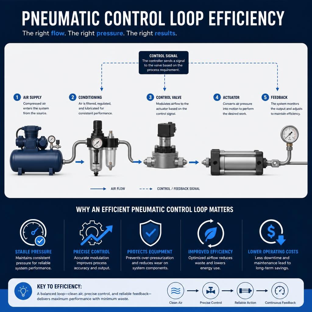
The air compressor one-way valve, while often small and unassuming, is a critical guardian of efficiency and longevity in any industrial pneumatic system. From ensuring the proper functioning of New England manufacturing facilities to optimizing complex automated processes globally, these valves are indispensable. Their fundamental role in preventing backflow, protecting compressor pumps from undue strain, and maintaining system pressure cannot be overstated.
As we have explored, understanding the various technical designs, material selections, and strategic placements of these valves across different compressor technologies is essential for robust system design and maintenance. Recognizing the signs of a faulty valve and implementing best practices for selection, sizing, and replacement are not merely maintenance tasks; they are proactive steps to safeguard valuable equipment and ensure uninterrupted operational flow.
For businesses seeking to maximize the performance and reliability of their pneumatic systems, leveraging expert application expertise is invaluable. Whether it’s selecting the precise components for new installations or optimizing existing infrastructure, partnering with specialists who understand the nuances of air compressor one-way valve technology and can provide custom assemblies can significantly enhance operational efficiency and reduce long-term costs. Investing in quality components and informed decision-making around these critical valves is a testament to a commitment to excellence in industrial automation.