Fundamental Principles of Current Transformers vs. Voltage Transformers
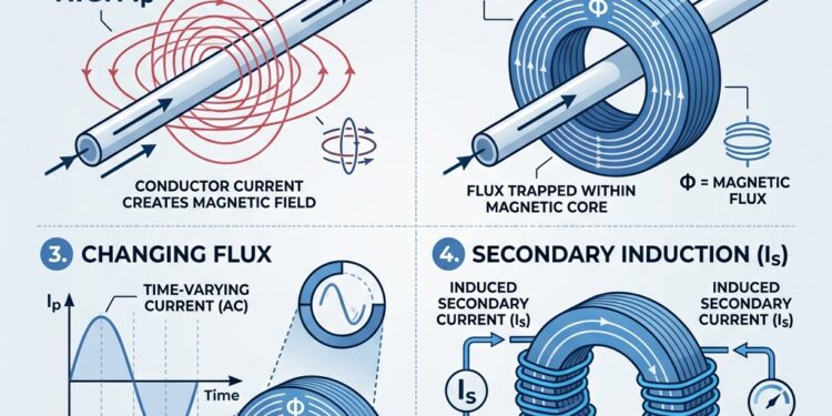
Table of Contents
- 1 Fundamental Principles of Current Transformers vs. Voltage Transformers
- 2 Engineering Reliable Instrumentation for Current in Transformers
- 3 Critical Safety Protocols: The Danger of Open-Circuited Secondaries
- 4 Performance Parameters: Accuracy Classes, Burden, and Saturation
- 5 Advanced Considerations: Excitation Current and Transient Dynamics
- 6 Frequently Asked Questions about Current in Transformers
- 7 Conclusion
Fundamental Principles of Current Transformers vs. Voltage Transformers
Current transformers (CTs) are vital parts of our electrical world. They help us manage high-voltage power safely. Without them, we couldn’t measure or protect our electrical grids.
These special devices change large currents into smaller, safer ones. This lets us use standard meters and protective relays. For Reliable instrumentation for current in transformers, understanding these tools is key.
In this guide, we will explore everything about current transformers. We will cover how they work, their different types, and why safety is so important. We will also look at how to pick the right one for your needs.

Join us as we break down the complex world of current transformers. We aim to give you a clear understanding of these essential components.
To truly grasp the essence of a current transformer, it’s crucial to understand how it operates and, equally important, how it differs from its counterpart, the voltage transformer (VT), also known as a potential transformer (PT). Both are classified as instrument transformers, designed to safely isolate high-voltage power circuits from measurement and control devices. However, their fundamental purpose and operational characteristics diverge significantly.
Feature Current Transformer (CT) Voltage Transformer (VT) Primary Connection Series with the load Parallel (across) the load Purpose Steps down current, isolates measurement from high current Steps down voltage, isolates measurement from high voltage Output Focus Proportional current output, largely independent of secondary voltage Proportional voltage output, largely independent of secondary current Secondary State Ideally short-circuited (low impedance) Ideally open-circuited (high impedance) Primary Turns Very few (often just one pass of the primary conductor) Many Secondary Turns Many Few Safety Risk Open-circuited secondary leads to dangerously high voltage Short-circuited secondary leads to high current and damage This table highlights the core distinctions between these two essential components. While both serve to scale down electrical quantities for safe measurement and protection, their design and application are tailored to their specific roles. For more detailed information about their voltage-handling counterparts, you can explore resources on Voltage Transformers.
Functional Differences in Design and Operation
The primary difference lies in their functional goals. A current transformer is designed to provide an output current directly proportional to the current flowing through its primary winding, largely irrespective of the secondary voltage. This means it acts as a current source. Conversely, a voltage transformer aims to provide an output voltage proportional to the voltage across its primary, largely independent of the secondary current, thus acting as a voltage source.
CTs are connected in series with the conductor carrying the current to be measured. Their primary winding typically consists of very few turns, sometimes just a single pass of the main conductor through a core (as in bar-type or toroidal CTs). The secondary winding, in contrast, has many turns. This configuration allows the CT to present a negligible load to the primary circuit, ensuring it doesn’t significantly impede the flow of the current it’s measuring. The current flowing through the primary is determined by the external load, not the CT itself. This principle is fundamental to current transformer basics.
VTs, on the other hand, are connected in parallel across the circuit whose voltage is to be measured. Their primary winding has many turns, while the secondary has fewer, stepping down the high voltage to a safe, measurable level. They aim to maintain a constant potential ratio, minimizing current draw from the primary circuit.
The Step-Down Principle and Turns Ratio
The step-down principle in a current transformer is governed by the turns ratio and the fundamental law of electromagnetic induction. When an alternating current flows through the primary winding (Np turns), it creates a varying magnetic flux in the CT’s core. This flux then induces an electromotive force (EMF) in the secondary winding (Ns turns), which, when connected to a low-impedance load (like an ammeter or relay coil), drives a proportional current (I_s).
The relationship between the primary current (Ip) and the secondary current (Is) is inversely proportional to the turns ratio:
Ip / Is = Ns / Np
This is often expressed as the Amp-turn equation, where the primary ampere-turns approximately equal the secondary ampere-turns: Ip * Np ≈ Is * Ns.
For example, a common CT ratio is 100/5, meaning that for every 100 Amperes flowing in the primary, 5 Amperes will flow in the secondary. This implies a turns ratio of 20:1 (Ns / Np = 100/5 = 20). If the primary current is 100A, the secondary current is 5A. If the primary current is 50A, the secondary current will be 2.5A.
Current transformers reduce high voltage currents to a much lower value, typically stepping down from thousands of amperes to a standard output of 5 Amps or 1 Amp. The secondary current of current transformers is usually rated at a standard 1 Ampere or 5 Amperes for larger primary current ratings. This standardization allows for interchangeable metering and protection equipment. For a 4000:5 CT ratio, a primary current of 4000A will produce a 5A secondary current. This precise proportionality is why CTs are indispensable for accurate current measurement and system protection. For a wide range of devices designed for precise current measurement, explore current transformers.
Engineering Reliable Instrumentation for Current in Transformers
The diverse applications of current transformers necessitate various designs, each optimized for specific installation and performance requirements. Understanding these types is crucial for selecting the appropriate device for any given scenario.
Types of Current Transformers
- Wound-Type CTs: These CTs have a primary winding physically wound around the core, similar to a conventional transformer. They are used for lower primary currents, typically 1 to 100 Amperes, where the primary circuit can be easily broken for installation. They offer high accuracy and are often found in laboratory settings or specific industrial applications.
- Toroidal (Window-Type) CTs: In this design, the primary conductor itself acts as the single-turn primary winding (N_p = 1), passing through a central opening (window) in the CT’s annular (ring-shaped) core. These are very common for higher primary currents (e.g., 100A to several thousand Amperes) and are highly efficient. They are often used in switchgear and motor control centers.
- Bar-Type CTs: Similar to toroidal CTs, but with a permanent bar conductor integrated as the primary winding, typically insulated for the system voltage. The main current-carrying conductor is bolted to the ends of this bar. They are robust and used in high-current applications.
- Split-Core CTs vs. Solid-Core CTs: This distinction is based on the core’s construction and its impact on installation.
- Solid-Core CTs: These have a continuously closed magnetic core, offering the highest accuracy and stability. However, they require the primary conductor to be disconnected and threaded through the CT’s window, making installation on existing, energized circuits difficult or impossible without downtime. They are preferred for new installations and revenue-grade metering.
- Split-Core CTs: These feature a hinged or separable core that can be opened and clamped around an existing primary conductor without interrupting the circuit. This makes them incredibly convenient for retrofit applications or temporary measurements. While generally less accurate than solid-core CTs due to the slight magnetic fringing and air gaps at the core’s mating surfaces, modern designs offer very respectable accuracy for many monitoring and energy management tasks. For flexible and easy-to-install options, consider Flex-Core FCL Series Flexible Split-Core Current Transformers.
Selecting Reliable Instrumentation for Current in Transformers for Metering
When selecting CTs for metering applications, accuracy is paramount, especially for revenue-grade metering where billing is involved. Metering CTs are designed to maintain high accuracy across a wide operating range, typically from 5% to 120% of their rated current.
Key considerations for metering CTs include:
- Accuracy Class: These are defined by standards like IEC 61869 or IEEE C57.13. For revenue-grade metering, classes like 0.2, 0.2s, 0.3, or 0.5 are common, indicating a maximum ratio error of 0.2%, 0.3%, or 0.5% respectively at rated current. Class 0.2s and 0.5s offer enhanced accuracy at lower currents (1% to 5% of rated current).
- Burden: The total impedance of the connected metering devices and wiring must not exceed the CT’s rated burden to maintain accuracy.
- Output Type: Traditional CTs output 1A or 5A. However, modern trends, especially in renewable energy and building management, favor 333mV output CTs. These provide a low-voltage signal proportional to the primary current, which is safer, reduces cabling costs (as lower current means less voltage drop over long runs), and simplifies integration with digital power meters. Devices like the Accuenergy ACUCT-3050-2000-333 Split-Core Current Transformer exemplify this technology, offering precise current measurement for energy management systems.
Installation Best Practices for Core Types
Proper installation is critical for both the accuracy and safety of CTs.
- Polarity: CTs have distinct polarity markings (e.g., H1/P1 and H2/P2 for the primary, X1/S1 and X2/S2 for the secondary). H1/P1 should face the source (line side), and H2/P2 should face the load. X1/S1 is typically the more positive secondary terminal. Incorrect polarity will result in reversed readings, which can cause protection relays to malfunction or meters to read incorrectly.
- Centering: For toroidal and bar-type CTs, ensure the primary conductor is centered within the CT’s window or aperture. Off-center placement can introduce ratio errors and phase displacement.
- Burden Matching: Always ensure the total burden of the connected secondary circuit (meter, relay, and wiring) is within the CT’s specified VA rating. Over-burdening a CT can lead to saturation and inaccurate readings.
- Secondary Wiring: Use appropriately sized and shielded twisted-pair cables for secondary connections, especially for long runs, to minimize interference and voltage drop. The IET Wiring Regulations provide guidelines for electrical installations, including considerations for instrument transformer wiring.
- Safety First: When installing split-core CTs on energized circuits, always follow strict safety protocols, including wearing appropriate personal protective equipment (PPE) and adhering to arc flash safety standards. While split-core CTs simplify installation by avoiding circuit interruption, the primary circuit remains live.
- Securing: Ensure CTs are securely mounted and, for split-core types, that the core halves are fully closed and latched, often with specific torque specifications to maintain magnetic integrity. Loose core halves can introduce significant errors (e.g., 10-30% inaccuracy).
For applications like current sensing in switched-mode power supplies, the selection criteria and design trade-offs for current sense transformers also emphasize careful consideration of turns ratio, core saturation, and accuracy.
Critical Safety Protocols: The Danger of Open-Circuited Secondaries
One of the most critical safety rules in electrical engineering pertains to current transformers: the secondary winding of a CT must never be left open-circuited while current is flowing in the primary. This is not merely a recommendation; it is a fundamental safety imperative that, if violated, can lead to severe equipment damage, dangerous high voltages, and serious injury or even fatality to personnel.
Why Secondary Windings Must Never Be Left Open
When a CT’s secondary winding is open-circuited, it effectively presents an infinite impedance to the magnetic flux produced by the primary current. According to Faraday’s Law of Induction, a varying magnetic flux induces an EMF. In a normally operating CT, the secondary current creates a magnetomotive force (MMF) that opposes the primary MMF, effectively limiting the net flux in the core to a very small value. This small flux is sufficient to induce the required secondary voltage to drive the secondary current through the connected burden.
However, if the secondary circuit is open, there is no secondary current to create this opposing MMF. Consequently, the primary current’s MMF drives the core into deep saturation. The magnetic flux density in the core rapidly increases to extremely high levels, far beyond its normal operating range. This highly concentrated and rapidly changing flux induces a dangerously high voltage across the open secondary terminals. These voltages can easily reach tens of thousands of volts (kilovolts), for instance, an open-circuited CT with a 480V primary could induce up to 76.8kV in the secondary, as observed in some cases.
The consequences of such high induced voltages are catastrophic:
- Personnel Safety: The high voltage poses an extreme electrocution hazard to anyone coming into contact with the open terminals.
- Equipment Damage: The insulation of the secondary winding is designed for low voltages (typically a few hundred volts). Exposure to kilovolts can cause immediate dielectric breakdown, leading to insulation failure and permanent damage to the CT.
- Arcing and Fire: The high voltage can cause arcing across the open terminals or to ground, potentially initiating fires.
- Core Damage: Prolonged operation in saturation can overheat and permanently damage the CT’s core material, rendering it inaccurate or unusable.
To prevent this dangerous condition, CT secondary windings are always short-circuited when not in use or when changing connected equipment. This is typically done using dedicated shorting blocks or shorting switches. Some advanced CT designs, like ProteCT™ technology, are engineered to produce very low voltage under open secondary conditions, mitigating some of these risks, but the general rule remains: never open the secondary circuit of an energized CT. This emphasis on safety is a cornerstone of transformer safety protocols. Furthermore, general guidelines for electrical safety, such as those found in testing of electrical leads and residual current devices (RCDs), underscore the importance of understanding and mitigating electrical hazards.
Performance Parameters: Accuracy Classes, Burden, and Saturation
The performance of a current transformer is defined by several key parameters that dictate its suitability for specific applications, whether for precise measurement or reliable protection. These parameters ensure the CT accurately reflects the primary current and operates safely within its design limits.
Accuracy Classes and Standards
CT accuracy is categorized by classes, which specify the maximum permissible error under defined operating conditions. These classes are standardized by international (IEC 61869) and national (IEEE C57.13) bodies.
- Metering CTs: Designed for high precision over a normal operating range (e.g., 5% to 120% of rated current). Common IEC classes include 0.1, 0.2s, 0.2, 0.5s, 0.5, and 1. The number indicates the maximum percentage ratio error at rated current. For instance, a Class 0.5 CT has a maximum ratio error of ±0.5%. The ‘s’ suffix denotes enhanced accuracy at lower currents. These are used for revenue metering and critical monitoring.
- Protection CTs: Designed to maintain reasonable accuracy over a much wider current range, extending into high fault currents (e.g., up to 20 times rated current). Their primary role is to provide a reliable input to protective relays during fault conditions. Common IEC classes include 5P and 10P. The number (5 or 10) indicates the maximum percentage composite error at the Accuracy Limit Factor (ALF). The ‘P’ stands for protection. For example, a 5P10 CT means it has a 5% composite error at 10 times its rated current. Protection CTs must handle at least 20 times their rated current without malfunctioning.
Other crucial accuracy factors include:
- Ratio Error: The deviation of the actual current ratio from the nominal ratio.
- Phase Displacement (Phase Angle Error): The phase difference between the primary current and the reversed secondary current. This is critical for power measurement and directional protection. For methods to correct this, refer to CT Phase Angle Correction.
- Knee-Point Voltage: This parameter, defined in standards like IEC 60050 – International Electrotechnical Vocabulary, is particularly important for protection CTs. It’s the secondary voltage at which a 10% increase in voltage causes a 50% increase in the magnetizing current. Beyond the knee point, the CT core begins to saturate, and its output becomes non-linear, meaning the secondary current no longer accurately reflects the primary current. Protection CTs are designed to operate linearly up to a certain multiple of their rated current (the Accuracy Limit Factor, ALF) before reaching the knee point, ensuring they provide accurate fault current information to relays. For detailed standards, consult IEC 61869-9:2016.
Calculating CT Burden for Proper Operation
The burden of a CT refers to the total impedance of the devices connected to its secondary winding, including the resistance of the connecting wires. It is typically expressed in Volt-Amperes (VA) at the rated secondary current, or in Ohms.
Why Burden is Critical: If the total burden connected to the CT secondary exceeds its rated burden, the CT will operate with a higher secondary voltage than designed. This can push the core into saturation even at normal operating currents, leading to significant ratio and phase errors. The CT will no longer accurately transform the primary current, compromising both metering accuracy and protection reliability.
Burden Calculation: To calculate the total burden (Ztotal): Ztotal = Zmeter + Zrelay + Z_wire
Where:
- Zmeter / Zrelay: The impedance of the connected metering or relaying devices (often specified in VA or Ohms by the manufacturer). If given in VA, convert to Ohms using R = VA / Is², where Is is the rated secondary current (e.g., 5A or 1A).
- Z_wire: The impedance of the secondary wiring. This is calculated based on the length of the wire run and its gauge (resistance per unit length). For example, for a 5A secondary CT, the wire resistance (Rwire) can be calculated as Rwire = (2 * lengthofrun * resistanceperfoot) / 1000.
- Example: For a 60/5A CT, like the RAM Meter Inc 2RL600 Current Transformer, if the connected meter has a burden of 0.1 Ohm and the wiring contributes 0.05 Ohm, the total burden is 0.15 Ohm. This must be less than or equal to the CT’s rated burden.
It’s crucial to ensure that the calculated total burden is always less than or equal to the CT’s specified rated burden.
Maintaining Reliable Instrumentation for Current in Transformers in Protection Systems
Protection CTs are designed to provide accurate current information to relays, especially during fault conditions where currents can be 10, 20, or even more times the normal rated current. Their ability to do this without saturating is paramount.
- High Accuracy Limit Factor (ALF): Protection CTs have a specified ALF (e.g., 10, 20, 30), indicating the multiple of rated current up to which they maintain their accuracy class. For example, a 5P20 CT will have a 5% composite error at 20 times its rated current.
- Saturation Prevention: Proper selection of a protection CT involves choosing one with an ALF and burden rating that ensures it will not saturate prematurely under expected fault current levels. Premature saturation means the relay will “see” a lower fault current than what is actually flowing, potentially delaying or preventing fault clearance, leading to equipment damage or system instability.
- Separate Cores: In many critical applications, separate CT cores are used for metering and protection. Metering cores are designed for high accuracy at normal currents and often saturate at lower fault currents to protect the meters. Protection cores are designed to remain linear up to very high fault currents to ensure relays operate correctly.
Protection CTs must handle at least 20 times their rated current without malfunctioning. This ensures that even under severe fault conditions, the protective relays receive reliable data to trip circuit breakers and isolate the fault. Solutions from companies like Power Electronics News often rely on robust CT performance for effective fault detection and system stability.
Advanced Considerations: Excitation Current and Transient Dynamics
Beyond steady-state operation, the performance of current transformers is significantly influenced by the subtle physics of their magnetic core, particularly under no-load conditions and during system transients. Understanding these phenomena is crucial for diagnosing CT behavior and ensuring reliable system protection.
Excitation Current in Transformers
Every transformer, including a CT, requires a small amount of current to establish the magnetic flux in its core. This is known as the excitation current (or no-load current), which flows in the primary winding even when the secondary is open-circuited. It’s composed of two main components:
- Magnetizing Current (Im): This component is responsible for creating the magnetic flux in the core. It lags the applied voltage by approximately 90 degrees. Due to the non-linear B-H magnetization curve of the core material, the magnetizing current is typically non-sinusoidal and “peaky” in shape. It can vary from about 0.25% to about 5% of full load current (0.05 pu) and can be as high as 10% in some special transformers.
- Core Loss Current (Ic): This component is in phase with the applied voltage and represents the energy dissipated as heat in the core due to hysteresis and eddy current losses. Typical core loss current (Ic) is around 1% of the full load current.
The excitation current is a critical factor affecting CT accuracy, as it represents the current that does not get perfectly transformed to the secondary. A CT’s magnetizing current is the primary source of its ratio and phase errors. For example, for a 4,000 kVA transformer, the excitation current is approximately 0.263% of the full load current.
The non-linear nature of the B-H curve means that as the flux density in the core approaches saturation, a disproportionately large increase in magnetizing current is required to produce a small increase in flux. This leads to the characteristic “peaky” waveform of the magnetizing current. This phenomenon is also closely related to transformer inrush current, which is essentially an extreme form of magnetizing current that occurs upon energization.
Harmonics: The peaky nature of the magnetizing current means it is rich in harmonics. The third harmonic current is approximately around 50% of the fundamental excitation current, the fifth around 15%, and the seventh around 1-2%. These harmonics are important in power quality analysis and in the design of protective relays.
Impact of Transients and Remanence Flux
During fault conditions or system disturbances, CTs are subjected to transient currents that can significantly affect their performance.
- DC Offset: When a fault occurs, the primary current often contains a transient DC component superimposed on the AC waveform. This DC component can drive the CT core into saturation very quickly, even if the peak AC component is within the CT’s linear operating range. This is because the DC component shifts the operating point on the B-H curve, effectively reducing the available flux swing before saturation.
- Remanence Flux: After a fault is cleared or a transformer is de-energized, the magnetic core can retain a certain amount of residual (remanent) flux. If the CT is re-energized with this remanence flux present, and the new operating conditions (e.g., switching angle) cause the flux to add to the remanence, the core can saturate much more easily. This phenomenon is quantified by the remanence factor (Kr), which is the ratio of the maximum remanent flux to the saturation flux.
- Inrush Current: Upon initial energization of a transformer, it draws a large, transient inrush current due to the sudden application of voltage to an unmagnetized (or previously magnetized) core. This current can be 5 to 30 times the full-load current (FLC) and is characterized by its high magnitude, decaying DC offset, and rich harmonic content (especially the second harmonic). While primarily associated with power transformers, the principles of core saturation during transients are relevant to CTs’ response to fault currents. Protection relays use techniques like second harmonic restraint to distinguish between inrush current (which has a high second harmonic content) and actual fault currents (which typically have low second harmonic content), preventing nuisance tripping during energization. Advanced techniques like point-on-wave switching are used to energize transformers at the optimal moment (typically voltage peak) to minimize inrush current by controlling the initial flux conditions.
These transient conditions and the presence of remanence flux are critical considerations in the design and selection of protection CTs, as they directly impact the ability of relays to accurately detect and clear faults.
Frequently Asked Questions about Current in Transformers
What is the difference between a metering CT and a protection CT?
The primary difference lies in their design philosophy and intended application.
- Metering CTs are designed for high accuracy over the normal operating range (typically 5% to 120% of rated current) to ensure precise measurement for billing and energy management. They often have accuracy classes like 0.1, 0.2, 0.3, or 0.5 (e.g., 0.3% error). They are designed to saturate at relatively lower fault currents to protect the connected meters from damage.
- Protection CTs are designed to maintain reasonable accuracy over a much wider current range, extending into high fault currents (e.g., up to 20 times rated current). Their main goal is to provide reliable input to protective relays during fault conditions, ensuring the relays operate correctly to clear the fault. They have accuracy classes like 5P or 10P (e.g., 5% composite error at 10 times rated current) and are built to withstand high fault currents without saturating prematurely. For more insights into these distinctions, resources like EEWeb often provide valuable comparisons between metering vs protection applications.
How does temperature affect CT accuracy?
Temperature can affect CT accuracy in several ways:
- Winding Resistance: As temperature increases, the resistance of the secondary winding (and primary, if wound) increases. This adds to the overall burden seen by the CT. If the total burden exceeds the CT’s rated burden, it can lead to increased errors.
- Core Permeability: The magnetic permeability of the CT’s core material can change with temperature. This alteration affects the magnetizing current and, consequently, the CT’s ratio and phase errors.
- Insulation Life: While not directly an accuracy factor, sustained high temperatures can degrade the CT’s insulation, reducing its lifespan and increasing the risk of failure. Manufacturers typically specify CT accuracy over a defined operating temperature range. It’s important to select CTs that can perform reliably within the expected ambient conditions of their installation.
Can a current transformer be used to measure DC?
No, standard current transformers are designed to measure only alternating current (AC). Their operation relies on the principle of electromagnetic induction, which requires a changing magnetic field to induce a voltage and current in the secondary winding. A direct current (DC) produces a constant magnetic field, which does not induce any current in the secondary.
To measure DC currents, different types of sensors are required:
- Current Shunts: These are precision resistors placed in series with the DC circuit. The voltage drop across the shunt is proportional to the DC current, which can then be measured by a voltmeter. For various options, consider exploring Current Shunts.
- Hall Effect Sensors: These devices utilize the Hall effect, where a voltage is generated across a conductor carrying current in a magnetic field. They can measure both AC and DC currents by detecting the magnetic field produced by the current.
- Fluxgate Magnetometers: These are highly sensitive devices that can measure static (DC) magnetic fields and are sometimes used in specialized DC current measurement applications.
Conclusion
Current transformers are indispensable components in modern electrical power systems, enabling safe and accurate measurement and protection. From the fundamental principles of electromagnetic induction and turns ratio to the critical safety protocols surrounding open-circuited secondaries, their design and application demand careful consideration.
We’ve explored the diverse types of CTs, distinguished between metering and protection applications, and delved into the intricacies of accuracy classes, burden calculations, and the impact of excitation current and transient conditions. By adhering to best practices in selection, installation, and maintenance, we ensure the reliable operation of our electrical infrastructure.
Understanding the nuances of current in transformers is not just an academic exercise; it’s a practical necessity for engineers, technicians, and anyone involved in the design, operation, or maintenance of power systems. For those seeking further knowledge and resources in electrical engineering, Electronics Know How serves as an excellent platform. As technology evolves, so too will the methods and capabilities of current measurement, but the foundational principles of CTs will remain at the heart of power system integrity.
Stay informed about the latest developments and insights in electrical engineering by choosing to Subscribe for updates.